Your first diagram
A diagram starts with three declarations: a model describes the entities and relationships, a stylesheet defines their appearance, and a view selects what to render.
This guide assumes meridian is available on your PATH. See
building from source if you need to set it up.
Describe a connected system
Save the following as system.mgl:
model system {
  client [Client]
  api [API]
  database [Database]

  request: client -> api [request]
  query: api -> database [query]
}

stylesheet blueprint {
  node {
    fill: #193e53
    stroke: #b7d5e5
    color: #f4eedf
  }
  edge {
    stroke: #b7d5e5
    color: #f4eedf
  }
}

view overview {
  use model system
  use stylesheet blueprint
}
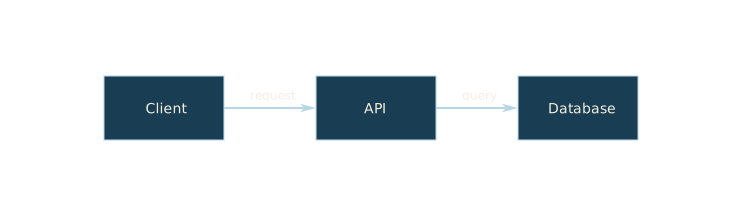
client, api, and database are stable IDs. The text in brackets is the visible
label. -> declares a directed relationship; request: gives that relationship
an explicit ID that can also be targeted by a stylesheet.
The view explicitly selects both the model and the stylesheet. Defining a stylesheet alone does not apply it to a view.
Render the view
meridian render --input system.mgl --view overview --output system.svgOpen system.svg in a browser or image viewer. The illustration above uses a
blueprint background supplied by this documentation site; that background is not
part of the diagram output.
Next steps
Read the MGL reference for the declaration structure, or try selectors and the cascade to highlight one node.